Cavity Ringdown Spectrometer Construction
at EIU
Dr. R. Peebles is building a cavity ringdown spectrometer which she will use to study species of atmospheric interest (CFC’s, SO2, NOx, H2O, etc.). In the first stage of construction, a spectrometer is being built which will function in the visible region of the spectrum. This will utilize a nitrogen pumped dye laser which is already available in the chemistry department at EIU. Once this system is running properly, the spectrometer will be adapted so that it functions in the IR region of the spectrum. This will involve incorporating a continuous wave laser so it will be more complicated than the initial design (since the dye laser is pulsed).
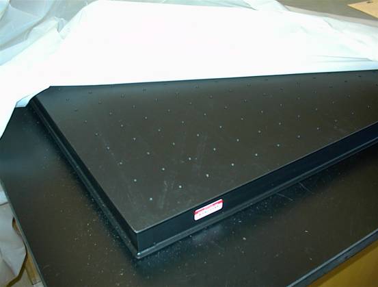
The construction of the spectrometer started shortly after I was hired, in the Spring of 2004. At that point I purchased a laser tabletop and a computer which will ultimately be used to control the spectrometer. LabVIEW 7 was also purchased to write software to control the instrument. A corner of the laser table sitting on the benchtop is shown below (left) next to a picture of the whole table sitting on the benchtop and covered with a tarp (right):
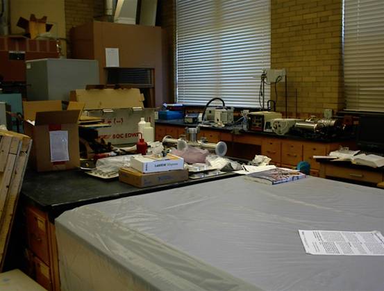
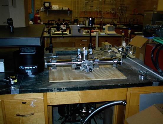
At this point I had to wait until some grant money came in so that I could start buying some more equipment. The buying really kicked in again in the Spring of 2005 when I bought components to construct the spectrometer chamber, a roughing pump, and a diffusion pump. In the picture above, the partially assembled chamber can just be seen in the middle of the photo, the Edwards RV5 roughing pump is on the bench behind it, and the diff pump (an Edwards Diffstak CR63) is lying on its side on the bench to the right of the chamber (between the windows). The chamber and diff pump are both stainless steel (and aluminum) and the roughing pump is grey and white painted steel and plastic. Close ups are shown below.
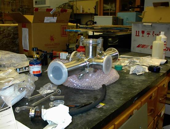
Here is the chamber. Click here for more pictures of the chamber in various stages of construction. The chamber is based on a six way cross with long arms attached to two sides to provide a long pathlength sample cell.
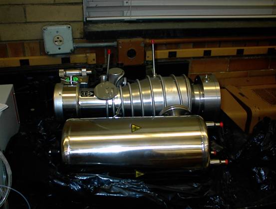
Here is the diffusion pump before putting it on the spectrometer. The smooth stainless steel cylinder is a liquid nitrogen Dewar which is used to chill a baffle within the pump and prevent backstreaming of gases and oil. More diff pump pictures are here.
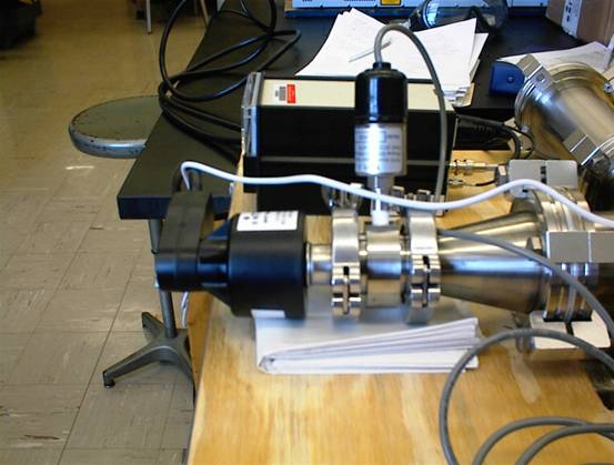
A framework was built out of steel and plywood to support the spectrometer with the diff pump attached. Then pressure gauges were bought and attached to the end of one of the arms. The sensor that sticks out the side of the arm is a thermocouple gauge and the sensor at the end of the arm is a cold cathode gauge (from MKS) which will measure down to about 10–8 torr.
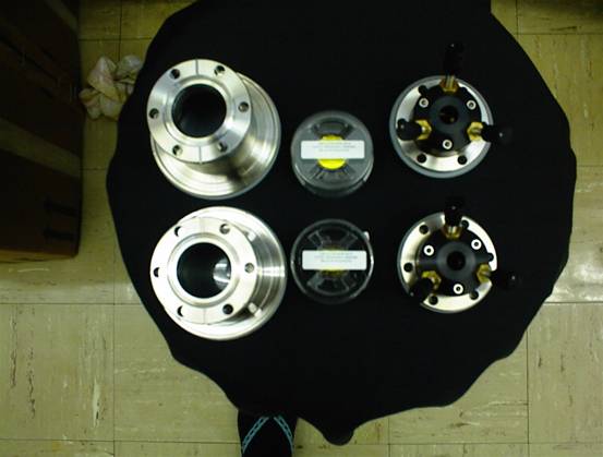
Mirrors and mirror mounts, along with adaptors to attach
them to the chamber, were bought but not immediately installed in the
chamber. The mirrors (from
In the Spring of 2006, a detector
was purchased and the spectrometer had to be moved to a more stable location
than the temporary framework that it had been sitting on. There was an old sink in the benchtop that had already had the taps removed, and this
seemed like the perfect place to suspend the chamber. The sink itself was removed and the EIU
stonemasons enlarged the hole where it had been by a couple of inches. A set of vibration damping legs was also
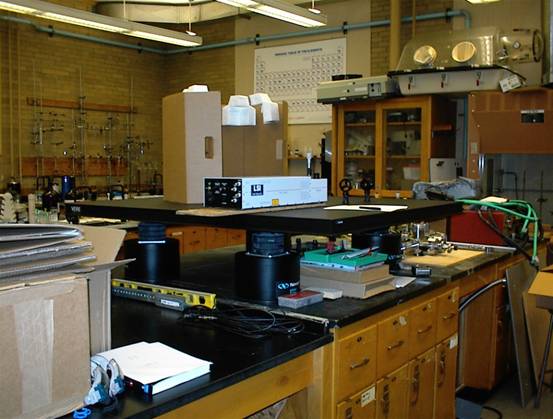
purchased so that the laser table could be moved off of the end bench and onto
the older bench next to where the chamber would be. The LabLegs (from
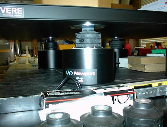
You can also see three smaller feet right at the bottom of the picture which are for supporting the chamber framework. Behind them is the foot pump that was included with the LabLegs (in its box). To elevate the chamber, the original framework was shortened and the small inflatable feet were bolted on the bottom. In order to modify the framework, we took the plywood off of the top of it and moved it, with the chamber, to sit in the old sink for a few days. All of this moving took quite a lot of muscle, so in addition to the help of Lawrence Keniley from my research group, Michal Serafin and Dr. S. Peebles were also roped in a few times. (Here is a picture of them trying unsuccessfully to make deuterated fluoroform.) Here is the chamber in its temporary position in the sink.
The foreline from the roughing pump can just be seen sticking up at the bottom of the photo above. There is a nice cubbyhole under the sink, and the plan was to put the pump in there. Here is the cubbyhole before the pump went in:
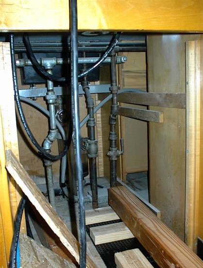
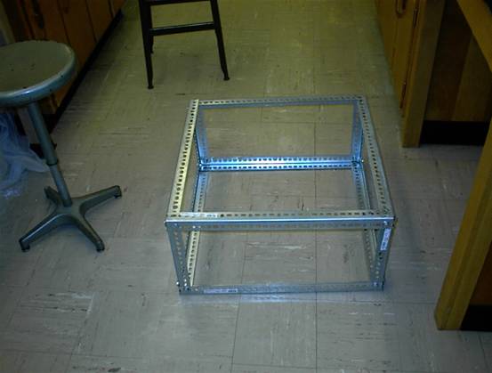
The bits of wood are parts of the platform which we built to raise the pump high enough that the foreline could connect with the raised up chamber. The new short version of the chamber framework is shown below:
In order to get the frame under the chamber, Mike and Larry had to lift it all the way up out of the sink and hold it there while Dr. S. Peebles and I got the framework in place (the feet were bolted on first). Then the plywood with the chamber on it was lowered back down onto the new frame. All of this involved a lot of feeding of electrical cords, which were hard wired into the diff pump, back and forth through the sink and the framework. The diffusion pump also had to be rotated 90° from its original orientation in order to fit in the sink. This was relatively easy since it is attached via a rotatable bolt ring. Here is the chamber on the finished frame:
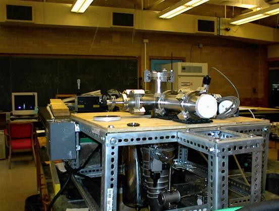
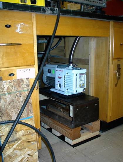
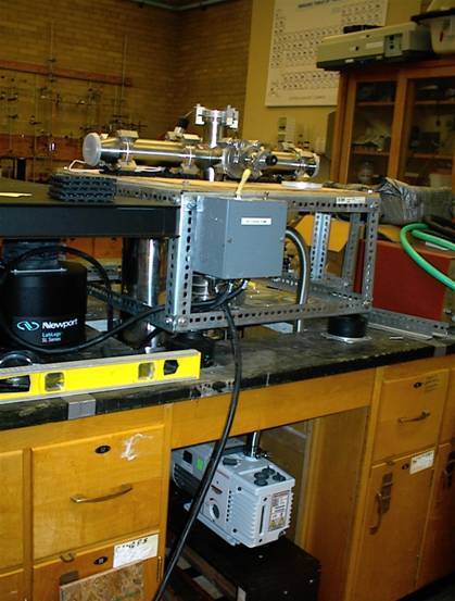
The feet are not visible since they blend in with the bench. You can also see a new piece which we added onto the near side of the frame to support a small breadboard which will hold the detector and associated optics. The grey box on the left side of the frame has a switch to control the diffusion pump and also has a reset switch in case the pump overheats and shuts itself off. With the chamber in place, the roughing pump could be reconnected. It is shown on the platform Larry constructed/modified in the picture below (left) and the entire chamber and pump assembly is shown on the right. The black stuff at the bottom is a piece of vibration damping mat, and each foot of the pump also sits on its own piece of mat. The orange box to the right of the framework (with the green hose on it) is the power supply for an old argon ion laser which was given to EIU by Oberlin college when they had to get rid of an old Raman spectrometer. We need to get the proper power and cooling water supplies in the lab before we can use the Ar ion laser.
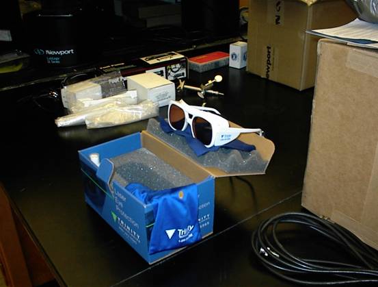
You can also see the vent valve for the chamber on the arm that sticks out toward the aisle. The next step is to align the laser and optics with the chamber, attach the mirrors, align again properly, line up the detector and hope for the best! In order to stay safe when aligning the laser, I bought a pair of laser safety goggles. Far out, man. (Or should it be “Elvis lives”?)
The laser on the laser table with some lens holders (so far without lenses) is shown below (left). This was when the chamber was in the sink. The picture on the right shows the chamber on the framework, and we are in the process of putting thicker plywood instead of thinner, splintery fiberboard under the laser. The black mat is mainly to prevent the laser from sliding around too easily. Note how quickly we managed to make use of the space under the laser table! The table has only been on the feet for about a week and a half at this point.
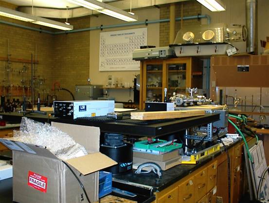
The stuff on the far side of the lab (which actually looks like a chemistry lab) belongs to Dr. Blitz’s group, who we share the lab with.
The most recent of these pictures were taken on June 8, 2006. Hopefully we will make lots more progress in the lab this summer, and this page should be updated as things progress!