

PHY1160C
Exam #1
September 15, 2000
Name ______________________________
![]()
This exam is fairly lengthy or long. Pace yourself accordingly. Do not spend too much time on any one problem.
It will be easy to spend too much time on the first two problems. Resist that temptation. Spread your time and efforts over all of the questions.
Possibly useful information:

k = 9 x 10⁹ N m2/C2
e = 1.6 x 10 - 19 C
me = 9.11 x 10 - 31 kg

PE = k Q q / r
V = k Q / r
Ceq = C1 + C2 + C3
P = IV = I2R = V2/R
Req = R1 + R2 + R3 + . . .
q = Qf e - t/RCi = Io e - t/RC
q = Qf [ 1 - e - t/RC ]i = Io [ 1 - e - t/RC ]
1. What is the electric field at
the origin (x = 0, y = 0) when charges
Q1 = - 10 µC and
Q2 = - 30 µC are placed at
corners of a square, 10.0 cm (0.10 m) on a side, as shown in the
figure below? What is the electric field -- magnitude
and direction -- at the origin?
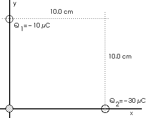
Diagrams always help,
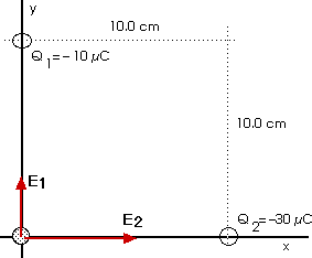
First we will calculate E1, the field due to charge Q1 and find its direction. Then we will calculate E2, the field due to charge Q2 and find its direction. Then we will find the vector sum of these two electric fields for the net field E.
![]()
E1 = 9.0 x 10 6 N/C and this field points upward. That is,
E1x = 0 E1y = + 9.0 x 10 6 N/C
Now for the field due to the other charge, Q2,
![]()
E2 = 2.7 x 10 7 N/C and this field points to the right. That is,
E2x = 2.7 x 10 7 N/C E2y = 0
The net field is the vector sum of these,
Enet = E1 + E2 which is shorthand notation for
Enet,x = E1x + E2x and
Enet,y = E1y + E2y
Enet,x = 0 + 2.7 x 10 7 N/C
Enet,y = + 9.0 x 10 6 N/C + 0
Enet,x = + 2.7 x 10 7 N/C
Enet,y = + 9.0 x 10 6 N/C
Enet,x = + 27 x 10 6 N/C
Enet,y = + 9.0 x 10 6 N/C
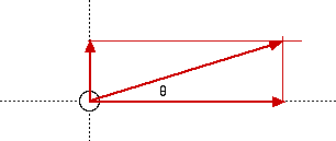
![]()
![]()
E = 28.5 x 10 6 N/C
![]() = 18.4°
= 18.4°
That is, the net electric field E isE = 28.5 x 10 6 N/C at the angle = 18.4o
as shown in the diagram.
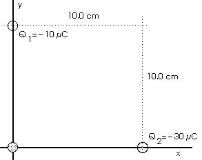
The electric potential due to a point charge is
Vtot =
Vi = V1 + V2
V1 = k Q1 / r1
V1 = ( 9 x 10 9 ) ( - 10 x 10 - 6 ) / 0.10
V1 = - 9 x 10 5 volts
V2 = k Q2 / r2
V2 = ( 9 x 10 9 ) ( - 30 x 10 - 6 ) / 0.10
V2 = - 2.7 x 10 6 volts = - 27 x 10 5 volts
Vtot = V1 + V2
Vtot = ( - 9 - 27 ) x 10 5 volts
Vtot = - 36 x 10 5 volts
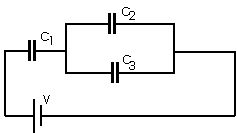
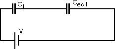
Ceq1 = C2 + C3 Ceq1 = (250 + 500)
F
Ceq1 = 750
F
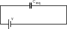

Ceq = 125
F
C = Q/V ===> Q = C V
Q = ( 125 x 10 - 6 F )( 12 V )
Q = 1.5 x 10 - 3 C
Now, for the total energy supplied by the battery,
PETot = [1/2] Q V = [1/2] [1.5 x 10 - 3 C] [12 V] PETot = 9 x 10 - 3 J = 9 mJ
Now we return to the individual capacitors,
Q1 = Q = 1.5 x 10 - 3 C
Note that the voltage across capacitor C1 is not 12 V !
V1 = 10.0 V This means the voltage across the parallel part, C2 and C3, must be
V2 = V3 = 12 V - V1 = 12 V - 10 V V2 = V3 = 2.0 V
Now, for the potentential energy stored in the capacitors,
PEcap = [1/2] Q V PE1 = [1/2] Q1 V1
PE1 = [1/2] ( 1.5 x 10 - 3 C )( 10 V ) = 7.5 x 10 &endash; 3 J = 7.5 mJ
PE1 = 7.5 mJ
Now for the other capacitors,
V2 = V3 = 2.0 V Note that V2 is not 12.0 V !
Q2 = C2 V2 = (250 x 10 - 6 F) (2.0 V) = 5 x 10 - 4 C = Q2 Q2 = 5 x 10 - 4 C = 0.5 x 10 - 3 C
Q2 = 0.5 x 10 - 3 C
PE2 = [1/2] Q2 V2 = [1/2] ( 5 x 10 - 4 C ) (2 V)
PE2 = 5 x 10 - 4 J = 0.5 mJ
V3 = 2.0 V
Q3 = C3 V3
Q3 = (500 x 10 - 6 F) (2.0 V) = 1 x 10 - 3 C
Q3 = 1 x 10 - 3 C
PE3 = [1/2] Q3 V3 = [1/2] ( 1 x 10 - 3 C ) (2 V)
PE3 = 1 x 10 - 2 J = 1.0 mJ
Notice that
PETot = 9 mJ = 7.5 mJ + 0.5 mJ + 1.0 mJ = PE1 + PE2 + PE3 and that
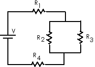
Resistors R2 and R3 are in parallel so we begin by replacing them with an equivalent resistor Req whose value we can calculate from1/Req = 1/R2 + 1/R3 = 1/(500 ) + 1/(1000
)
1/Req = (0.003) /
Req = [1/0.003]
= 333.3

[ Notice that Req < 500
or that Req < Rmin; that is, notice that the equivalent resistance Req is less than the smallest (or smaller) of the resistors in parallel. ]
Now we have R1, this Req, and R4 in series as in the following diagram,
or
The new equivalent resistor Req,2 for this combination of three resistors in series is given by
Req,2 = R1 + Req + R4 Req,2 = 100
+ 333
+ 400
Req,2 = 833
The current from the battery is given by
I = V / Req,2 = 12 V / 833 = 0.0144 A
This is the current through R1 and R4,
I1 = I4 = 0.0144 A The power supplied from the battery is
P = I V = (0.0144 A)(12 V) = 0.173 W Pbat = 0.173 W
Now we work back and find the power absorbed by each of the resistors (well, at least find the power absorbed by resistor R1 since that was asked for in this question). We know the current through R1 and R4 so we can find the voltage across them and then find the power absorbed by them.
V1 = I R1 = (0.0144 A)(100 ) = 1.44 V
P1 = I V1 = (0.0144 A)(1.44 V) = 0.021 W
Only I1 ( = 0.0144 A) and P1 ( = 0.021 W) were asked for in this question. We have found those now. The required solution is complete.
But we might as well continue and find the current and power for all of the resistors -- just for "completness".
V4 = I R4 = (0.0144 A)(400 ) = 5.76 V
P4 = I V4 = (0.0144 A)(5.76V) = 0.0829 W
The voltage across the bank of resistors in parallel -- R2 and R3 -- is the 12 V of the battery minus the voltage across R1 and R4,
V2 = V3 = 12 V - 1.44 V - 5.76 V = 4.80 V P = I V = (V / R) V = V2/R
P2 = (4.80 V)2 / (500
) = 0.0461 W
P3 = (4.80 V)2 / (1000
) = 0.023 W
I2 = V2/R2 = 4.80 V / 500
= 0.0096 A
I3 = V3/R3 = 4.80 V / 1000
= 0.0048 A
As a quick check, see if these absorbed powers equal the battery's output power,
Ptot = P1 + P2 + P3 + P4 Ptot = (0.021 + 0.0461 + 0.023 + 0.0829 ) W
Ptot = 0.173 W = 0.173 W = Pbat
And that agrees to three significant figures. This agrees with our ideas of energy conservation.
We have calculated all of the currents
Notice, too, that
as we would expect from Kirchoff's Jucntion Rule or simply from charge conservation
a) What is the final charge Qf that will accumulate on the capacitor in this circuit, after switch S is closed, if we wait long enough?R = 2000
C = 500 µF
V = 12 vb) What is the time constant of this circuit?
c) What charge will there be on the capacitor 2.0 s after the switch is closed?
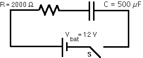
After a long time, the current will be zero because the voltage across the capacitor will just "balance" the voltage of the battery,Vf = 12 v C = Q / V
Qf = C Vf
Qf = ( 500 x 10 - 6 F ) ( 12 v )
Qf = 6.0 x 10 - 3 C
The time constant of this circuit is
= RC
= ( 2000
) (500 x 10 - 6 f )
= 1.0 s
The charge on the capacitor, as a function of time, is
q = q(t) = Qf [ 1 - e - t / ]
q ( 2.0 s) = q (t = 2.0 s) = Qf [ 1 - e - 2.0 /
]
q ( 2.0 s) = Qf [ 1 - e - 2.0 / 1.0 ]
q ( 2.0 s) = Qf [ 1 - ( e - 2 ) ]
q ( 2.0 s) = Qf [ 1 - ( 0.135 ) ]
q ( 2.0 s) = Qf [ 0.865 ]
q ( 2.0 s) = 0.865 Qf
q ( 2.0 s) = 0.865 ( 6.0 x 10 - 3 C )
![]()