

Phasor Diagrams
We can understand AC circuits in terms of phasor diagrams. Here a vector of length Vo rotates with angular velocity
. Its projection onto the vertical axis is
v = Vo sin t
and that is just the AC voltage from a generator or a power supply.
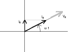
The current iR through a resistor R is in phase with the voltage vR across the resistor so we may show that on a phasor diagram by drawing a vector IR which lines up with the voltage VR.
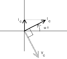
The current iC through a capacitor C is ahead of the voltage vC across the capacitor by 90 degrees so we may show that on a phasor diagram by drawing a vector IC which leads the voltage VC by 90 degrees.
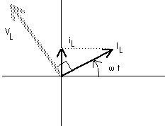
The current iL through an inductor L is behind the voltage vL across the inductor by 90o so we may show that on a phasor diagram by drawing a vector IL which lags the voltage V by 90 degrees.
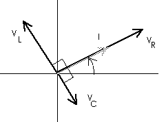
At any given time, the sum of the voltages across the three components, R, C, and L, must equal the voltage of the AC source. This is just energy conservation or Kirchoff's Loop Rule,
v(t) = vR(t) + vC(t) + vL(t) or
v = vR + vC + vL Remember that the phase relationship between the AC voltage v and each of the other voltages differs for each of the voltages. We can handle this graphically with the following phasor diagram:
or
For convenience, we may want to rotate this diagram,
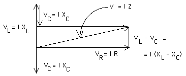
Now we can see that the voltages form the sides of a right triangle with the voltage of the AC source forming the hypotenuse. That means
V = I SQRT[ R2 + (XL - XC)2 ] or, since V = I Z, we can now write the total impedence for this series RCL circuit as
Z = SQRT[ R2 + (XL - XC)2 ] where R is the resistance, XC is the capacitive reactance, and XL is the inductive capacitance.
[ Of course, the "SQRT" needs to be replaced with a properly written radical sign in the equations].
(c) Doug Davis, 2002; all rights reserved


Return to ToC