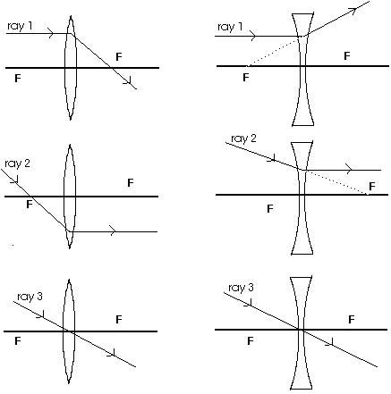
As with mirrors, we will find it extremely useful to look at three
principal rays because it is easy to predict their behavior. They
are sketched in Figure 18.16 and are very similar to the principal
rays we have already seen in our study of mirrors. Ray 1 is an
incoming ray parallel to the optic axis. For a converging lens,
ray 1 is bent or refracted and passes through the focal point
on the other side of the lens as shown. For a diverging lens,
ray 1 is bent or refracted away from the optic axis and leaves
the lens as though it originated from the focal point on the incoming
side of the lens. Ray 2 is just the reversal of this ray. For
a converging lens, ray 2 has passed through the focal point in
front of the lens. It is bent or refracted, leaving the lens parallel
to the optic axis. For a diverging lens, ray 2 is headed toward
the focal point on the opposite side of the lens. It, too, is
bent or refracted, leaving the lens parallel to the optic axis.
Ray 3 passes through the center of the lens undeviated. The reason
is the two surfaces of the lens at the optic axis are parallel!

Figure 18.16 Three principal rays will be very
useful in understanding the formation of images.
We will now do with lenses what we earlier did with mirrors-their
role in image formation is similar. Figure 18.17 shows an object
placed some distance from a converging lens. We have again used
a simple arrow. The tail of the arrow is again on the optic axis.
An infinite number of rays leave the tip of the arrow but we will
concentrate on only the three principal rays we have just defined.
Having a real image means that all of the rays that leave the
object and go through the lens will pass through a single point
that locates the image. Figure 18.18 shows more ray diagrams for
real images produced by various object distances.

Figure 18.17 Ray diagrams locate a real image.
All the rays that leave a point on the object and go through the
lens will pass through a common point if a real image is formed.
For efficiency and convenience we concentrate on the three principal
rays.


Figure 18.18 As the object is moved in from far
away, the real image produced becomes larger, and is upside down.
When the object distance is twice the focal length, the size of
the image is the same as the size of the object; the image is
still real and upside down. As the object moves closer to the
focal point, the image size becomes larger than the object size.
Just as with mirrors, the magnification is the ratio of the image
height to the object height. If Figures 18.17 and 18.18, when
the object is far away, the image is smaller in size and is upside
down so the magnification is small and negative, like M = - 0.50
or M = - 0.75. When the object distance is twice the focal length,
the image is the same size as the object and is upside down so
the magnification is M = - 1.00. As the object moves closer than
this, the image increases in size but remains upside down so the
absolute value of the magnification continues to increase although
the magnification is still negative.
Figures 18.17 and 18 show a real image produced as long
as the object distance is greater than the focal length. For a
real image, the light actually passes through the image. If a
card or screen is placed at the location of the image, an image
will be projected on the card or screen. But a lens can also produce
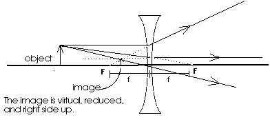
a virtual image. Figure 18.20 shows two examples of a lens producing
a virtual image. One is with a converging lens; the other, a diverging
lens. Converging lenses can produce either real or virtual images
from a real object depending upon where the object is. If the
object is beyond the focal point the converging lens will produce
a real image; if the object is inside the focal point, a virtual
image will be produced. Diverging lenses produce only virtual
images from real objects. The virtual image, as before, can be
seen quite clearly and looks like the object. But it can not be
projected; that is what a virtual image means.

Figure 18.19 When the object is between the converging
lens and the focal point, a virtual image is produced.

Figure 18.20 Ray diagrams locate a virtual image.
All the rays that leave a point on the object and go through the
lens leave as if they came from a common point when a virtual
image is formed. We concentrate on the three principal rays because
they are easy to handle. The dotted lines indicate where the light
rays appear to have come from.
For virtual images formed by a single lens, the virtual image
will always be right side up so the magnification will be positive.
In the first examples of Figure 18.20, with a virtual image formed
by a converging lens, the virtual image is larger than the object
so the magnification is greater than one (M > 1.00). In the
second example, with a virtual image formed by a diverging lens,
the virtual image is smaller than the object so the magnification
is smaller than one (M < 1.00).


Figure 18.H Converging lenses can produce enlarged or
reduced images, depending upon the distance of the object from
the lens.
Q: What kind of images can be produced by a converging
lens?
A: Figure 18.18 illustrates several real images
produced by a converging lens. By varying the object distance,
the image may be reduced or enlarged in size. Figure 18.19 illustrates
a virtual image produced by a converging lens.
Q: What kind of images can be produced by a diverging
lens?
A: For a real object, a diverging lens produces
only a virtual image that is reduced in size; this is illustrated
in Figure 18.20.


